顯示具有 LF-BOX1 標籤的文章。 顯示所有文章

2016年2月13日 星期六

[Locationfree] 製作紅外線遙控轉換器 IR translator LF-BOX1 Panasonic CATV/DVD 轉 Tivo

上一篇 [Arduino] 製作紅外線遙控轉換器 IR translate Panasonic 電漿電視轉 Kbro 凱擘 , 最近用同樣的原理製作了 LF-BOX1 的紅外線遙控轉換器, 把 LF-BOX1 所發出的 Panasonic CATV(1)/DVD(1) 紅外線碼轉換為 Tivo 紅外線遙控碼, 這樣可以讓 LF-BOX1/LF-PK20 的組合遙控原本不支援的 Tivo.

首先簡單說明一下 Sony LF-BOX1 和 LF-PK20 日版之間的使用關係, Locationfree LF-PK20 是 server 端, 可以將 AV 端子輸出的器材轉換成為網路串流, 讓使用者透過 Intranet 或 Internet 看電視. 由於 LF-PK20 是 server 端, 所以需要一個 client 端, 通常是安裝在 Windows 上的 Locationfree player 軟體. 除此之外, 對於日版 LF-PK20 (只有日版)還有另一種選擇就是 LF-BOX1 這樣的專屬 client 端設備, 它可以透過網路連接遠端的 LF-PK20 server, 並且透過 AV 端子輸出到電視上, 達成遠端看電視的目的. LF-BOX1 也是在 LAN 下輸出畫質最好的一個 Locationfree client.

連接關係是這樣:

Video Output path:
set-top box (ex. Tivo or Kbro) ---[AV]---> LF-PK20 ---[LAN/WAN]---> LF-BOX1 ---> TV

User IR Input path:
User press remote ---> LF-BOX1 ---[LAN/WAN]---> LF-PK20 ---> set-top box (ex: Tivo or Kbro)

事實上, LF-BOX1 中內建有和 Tivo 很接近的遙控碼可以使用, 但有缺點就是上下鍵會吐兩次 IR code 造成 Tivo 選節目的時候一次跳兩格, 相當惱人. 而且也不支援 Tivo 的數字鍵選台. 所以想透過製作紅外線遙控轉換器把某個 LF-BOX1 內建發出的 IR code 轉換成為 Tivo 紅外線碼. 這樣在遠端就可以遙控 Tivo 選擇節目或者選台.

IR 遙控路徑變成這樣:
User press remote ---> LF-BOX1 ---[LAN/WAN]---> LF-PK20 ---> Arduino IR Translator  ---> set-top box (ex: Tivo or Kbro)

我製作的 Arduino 轉換器就是串接在 server 端的 LF-PK20 和 LF-PK20 附帶的 IR 發送器 (IR emitter) 之間. 它的構造就是 IR Detector + IR Emitter.

轉換作用像這樣:

LF-BOX1 ---> LF-PK20 --- [Panasonic DVD(1) code] ---> Arduino IR Translator ---> [Tivo code]

我在 LF-BOX1 上面選擇的遙控碼為 松下 CATV(1) 和 DVD(1), 我曾試過 Sony 的 IR code, 但發現 Arduino 的 IRremote library 讀取 Sony IR code 作出的 hash code 會有碰撞的狀況, 也就是數個按鈕可能會抓到同一個 hash code, 造成無法判斷使用者按了哪個鍵. 另外, 使用 Sony 的過程有發現當 IR detector 和 IR emitter 寫在同一支程式中, 像我現在的應用就是需要同時使用 detector 和 emitter, 則 IRremote 寫出來的程式所發出的 IR code 會失敗. 至於原因我並沒有探究, 總之改為抓 Panasonic code 就 OK 了.

下面就是把 LF-BOX1 中的遙控碼設定為 Panasonic (松下) CATV(1) 另外次遙控器設定為 DVD(1). 會 mapping 兩組的原因是因為有時候給家中其他人使用如果不需要太複雜太多的功能, 用 CATV(1) 就可以了, 如果需要遙控或者快轉等功能則 DVD(1) 的按鍵比較多:


先用麵包板測試一下 LF-BOX1 的 IR emitter 座的腳位定義, 也就是故意將 LF-BOX1 附贈的 IR emitter 接到 Arduino 上面, 利用 Arduino 透過它發送 IR code, 如果用數位像機看到 IR LED 有亮起來, 就代表可以控制:

OK, 透過數位像機可以看到紅光, 代表 IR LED 有亮起來:

立體聲腳座的定義, 靠外側黑色是接地, 內側紅色是供電:

知道腳位定義後, 以相同的腳位把一顆 IR LED 焊接到立體聲座上:

另外這此我使用的 IR detector 是 VS-1838B:

我的 IR detector 接到 Arduino pin 12, IR emitter 接到 pin 3 (IRremote 的預設). 並且用一個零件盒裝起來. 當然要記得開三個洞, 一個給 IR LED, 一個 IR emitter, 然後是供電的 USB:

IR LED, 這端接到 LF-BOX1 上的 IR emitter 座:

近照部分電路與 USB 取電座:

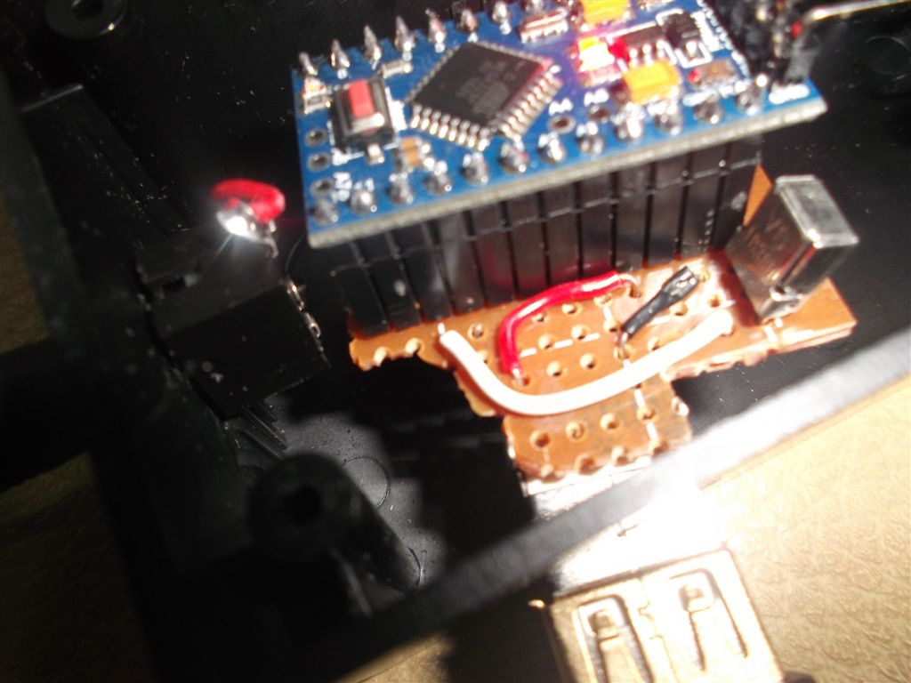
硬體這樣就完成了. 原始的 LF-PK20 配置像下圖. 它附帶的 IR emitter 直接接到 IR 座. 事實上它可以接兩個 emitter, emitter 也可以自己做:


改為把我做的 IR translator 接到 LF-PK20 上, 然後 IR emitter 接到自製的 IR translator 上. 別接錯孔, 接錯動不了:

近照:

另一個方向, USB還沒有接電:

IR LED 端近照:

整體:

硬體這樣就完成了. 軟體部分已上傳 github:
https://github.com/smallbeetw/arduinosketch/commit/75a61430bfcdfcc47470b8a4cee575e6e0c1d2cf

下面是另一個試作品, 這個試作品是沒有用黑盒子把電路裝起來, 直接做了一個 IR LED 和 立體聲公頭 焊接在一起的 IR emitter, 插到 LF-PK20 上發射 IR code, 然後用另一個裸露的電路板接收, 這個做法堪用但比較差, 原因是因為接收器可能會接收一般其他遙控器的 IR code, 這樣比較耗電.

下面組圖就不解釋了, 有需要就參考著做, 只要腳位弄對, 插到 LF-PK20 上就可以使用. 我沒有串電阻, 如果需要可以串上;

注意腳位, 黑的接 LED 短腳, 紅的接 LED 長腳:


完成後插到 LF-PK20 上, 用數位像機確認:

2015年1月13日 星期二

[Arduino] Use IRrepeator to capture IR raw code of kbro TV box's remote control

[Arduino] 用 IRrepeater 抓取 kbro 凱擘遙控器的 IR raw code (Chinese)

Due to Sony Locationfree already stop supported by Sony. My kbro TV box's remote control IR code set didn't in out-of-box IR code set of Locatoinfree, that causes I can not using Locationfree to control TV box. And, the Locationfree LF-BOX1's out-of-box IR code set is also limited, except it doesn't support kbro TV box, some buttons of Tivo's remote control also doesn't work.

So I want using Arduino to make a IR translator. To translate the Tivo IR code that emitted by Locationfree to be the IR code of kbro box. Then Locationree can support any new TV box through this Arduino translator. The same feature is also useful on Slingbox, you don't need worry for how to create the Slingbox bin file for new IR code.

Before making IR translator, grab the IR codes of remote control of Tivo and kbro is the most important preliminary work. This article introduces how to capture IR code by Arduino. The traditional method is using IRrecvDump in IR remote library of Arduino to capture IR codes. But, it doesn't work to kbro's remote control. I will introduce another useful way to grab the IR code, that's using IRreperter program.

First, I still using the most popular program, IRrecvDump to capture code. The following picture is my wire layout of breadboard: I used 3 pin stereo connector to connect to IR receiver. The red wire connected to 5v output pin of Arduino nano, black wire connect to GND pin, white wire connect to digital 11 pin for data input:


More detail: Red wire to 5V, Black wire to GND, White wire to D11

Runing Arduino IDE, select Arduino Nano w/ ATmega328 in "Board" selection:

More detail steps please google, there have bunch of articles introduced that. Please remember copy IRremote library to libraries folder in Sketchbook then Arduino IDE can find it when restart.

Please open IRrecvDump example in IRremote library, compiler and upload to Arduino. Then please launch Serial monitor to watch the IR code that captured. The printing result as following:

Decoded NEC: A10C7807 (32 bits)
Raw (68): -23088 8950 -4450 550 -1650 550 -550 550 -1650 550 -550 550 -550 550 -550 550 -550 550 -1650 550 -550 550 -550 550 -500 600 -500 550 -1650 550 -1650 550 -550 550 -550 550 -550 550 -1650 550 -1650 550 -1650 550 -1600 600 -500 550 -550 550 -550 550 -550 550 -550 550 -550 550 -550 550 -550 550 -1650 550 -1650 550 -1650 550
A10C7807

If program parser IR code type success, it will print out the type like the above NEC words, and follow a hash number of raw code and raw code data. You can using IR type and hash number, or direct using raw code. If it didn't parser out type, you still can using raw code with raw length to emit IR code. Please write down those codes.

When using Raw code, plesae remove the first number. As the above example, -23088 should discarded, please don't paste to your IRsend program. Then please modify all negative number to positive number, the whole length is 68-1. Then you can paste whole raw numbers to IRsend code to be a unsigned int array for testing. As the above example, it will be like:

8950 4450 550 1650 550 550 550 1650 550 550 550 550 550 550 550 550 550 1650 550 550 550 550 550 500 600 500 550 1650 550 1650 550 550 550 550 550 550 550 1650 550 1650 550 1650 550 1600 600 500 550 550 550 550 550 550 550 550 550 550 550 550 550 550 550 1650 550 1650 550 1650 550

Paste those numbers to program to be array, please remember add comma between 2 numbers. The code like this:
https://github.com/smallbeetw/arduinosketch/blob/master/Panasonic2KbroIRtrans/Panasonic2KbroIRtrans.ino#L50

The following are IR coddes of Tivo's Channel up/down button. I do not list raw code because Arduino captured the NEC type has no problem:

TIVO
    Channel up:        NEC: A10C7807 (32 bits)
    Channel down:    NEC: A10CF807 (32 bits)
Remote control of Tivo like this:


After got IR odes, then we cn try to using IR LED to emit IR code for receiving by devices (TV or set-top box). If devices done corresponding action after received IR code, that menas the code is correct. The layout of breadboard is really simple. Just connect the long pin of IR LED to D3, the short pin to GND:


Here is s stupid story of me.  The first time I try IR LED, I direct connect the long pin to 5v ouptut fro Arduino, then LED blasted immediately. That's my first time saw the LED blasted, it's dangerous to my eyes.
As you see in the above picture, I didn't add resistance in long pin because current didn't continue output through D3 pin, so should not like direct connect to 5v pin. But, add resistance is still a better idea for safety

The sofeware of emit IR code is easier than dump, just need jsing IRsendDemo in Arduino IDE. Modify the code type and hash number. Compiler and upload to Arduino, open Serial Monitor and key-in any character to trigger IR code emitting.  Waiting the reopnse of set-top box to verify the code correct.

if you wan to check does IR LED really work. Due to infrared ray could not see by human being. You can using a digital camera to monitor it.

The above steps is the popular way from internet to capture IR code through IRrecvDump. But this way doesn't always work, some remote control's codes are hard to capture by IRrecdump. I don't know why, maybe that has problem in IR remote library. I am not a IR expert, and I am no oscilloscope to check that.

Unfortunately,the remote control of kbro TV box on my hand is this kind of thing:


For grab the IR code of kbro remote control, I spend whole day until 2 am. Finally I find the way to capture IR code more easily. I modified my IR repeater program, add codes for print out IR raw code:
https://github.com/smallbeetw/arduinosketch/blob/master/IRrepeator/IRrepeator.ino

The advantage of this program is like merged IRreceDump and IRsend. That means Arduino grab the raw code then emit immediately through sendRaw() from IR LED. So, I call it IRreperter. This kind of device sale on many store on internet. It's useful to extend the IR receive window on device. e.g. if the IR receive window of TV covered by speaker, or DVD player put in cabinet. Then this device is useful to repeat IR code to other direction or space.

The breadboard layout as following, just put IR receiver and IR LED on the same board:

The simply circuit as following:


The benefit of IRrepeater is for some remote control that Arudino SOMETIME can capture IR code, but the success rate is not too high. Then we can just put button continuously, IRrepeater will emit IR code to set-top box continuously until we saw box response the code. Then we can confirm the code is valid and write it down.

Simply say, when using IRreperter, user can test the raw code immediately. Don't like the IRreceDump, need paste raw code to IRsend program to check, then using IRrecvDump capture again if the code invalid.

Through this way, I captured raw code of the channel up/down button, I will post other keys when I have time. (found the fail rate is really high for grab the code of kbro remote control):

KBRO
  Channel UP:         250,850,250,1000,250,700,250,750,200,750,250,2450,250,750,200,750,250
  Channel DOWN:   250,850,250,850,250,750,200,750,250,700,250,2600,250,750,200,750,250

I used 
sendRaw(sendRawCodes,17,38), and add delay(40). Confirm the above codes are available. Some information from internet say the 38 hz for IR is because this frequency does not use in the nature, it can avoid too many noise.

Except the way to use IRreperter to grab the remote control for SOMETIME work. Some other solutions may worth to try: like some Sony remote control used 40 hz, or Samsung's raw code length sometimes longer then the default size of RAWBUF 100 (Please modify the RAWBUF length define in IR remote library from 100 to 400). And set a longer delay when testing, using 1000 to avoid too fast to emit next code of next cycle. The above are some hints from internet that can try when IRrecDump doesn't work to you.

In this time, I also capture the IR codes of Sony Locationfree LF-Box1's RM-Box1 remote control. This remote control is special and not easy to find on market. So, list the IR codes here for reference:


RM-BOX1
  UP:                    Decoded SONY: 4EB31 (20 bits)
  DOWN:             Decoded SONY: CEB31 (20 bits)
  LEFT:                 Decoded SONY: AEB31 (20 bits)
  RIGHT:               Decoded SONY: 2EB31 (20 bits)
  決定:                  Decoded SONY: 6EB31 (20 bits)
  畫面xxx:             Decoded SONY: 14B31 (20 bits)
  右下:                   Decoded SONY: 34B31 (20 bits)
  左上:                   Decoded SONY: ACB31 (20 bits)
  戾xxx:                  Decoded SONY: 54B31 (20 bits)
  電源:                   Decoded SONY: A8B31 (20 bits)
  入力切換:           Decoded SONY: A4B31 (20 bits)
  畫面表示:           Decoded SONY: 44B31 (20 bits)
  設定:                   Decoded SONY: 4B31 (20 bits)
  XXX電源:           Decoded SONY: A90 (12 bits)
  入力切換(左上): Decoded SONY: A50 (12 bits)
  音量(+):               Decoded SONY: 490 (12 bits)
  音量(-):                Decoded SONY: C90 (12 bits)
  消音:                    Decoded SONY: 290 (12 bits)

more: 
[Arduino] Make a IR translator to translate IR code of Panasonic TV to Kbro TV box

2014年12月1日 星期一

[Arduino] 用 IRrepeater 抓取 kbro 凱擘遙控器的 IR raw code

[Arduino] Use IRrepeator to capture IR raw code of kbro TV box's remote control (English)

2016-03-15 update:
本文的方法只能抓到部分凱擘遙控碼, 完整抓法請參考下文:
[Arduino] 完整抓取 凱擘 kbro 遙控器紅外線原碼並發出重新發出以控制機上盒 (NEW)

由於 Sony Locationfree 已經停止支援, 內建的 IR code 找不到支援 kbro凱擘數位機上盒的 code set. 造成無法使用 Locationfree 選台, 而且 Loctionfree LF-BOX1 內建的 IR code 也是有限, 除了 kbro 機上盒不支援以外, 對於 Tivo 的支援也有很多按鍵無法使用.

所以我一直想用 Arduino 做一個 IR 轉譯器(IR translater)的功能, 把 Locationfree 發出來的 Tivo IR code 轉為 kbro IR code. 這樣一來靠一個 Arduino 轉換器就可以讓 Locationfree 支援各種新的機上盒. 同樣的功能也能用在Slingbox上, 不用苦惱為了得到 IR code 的 bin file 到處求爺爺告奶奶.

在製作 IR translater 之前, 抓取 Tivo 和 kbro 遙控器的 IR code 是重要的先遣工作. 本篇文章介紹如何抓取 IR code. 特別的是, 用傳統網路上找到的方法都是用Aurdino IR library 內建的 IRrecvDump 來作為抓取程式, 但是遇到 kbro 這種特別"高拐"的遙控器就抓不出來. 所以我這裡另外介紹一個自創的方法更方便去抓出正確的 IR raw code, 就是使用 IRrepeater 程式.

首先還是先用大家最常用的 IRrecvDump 來抓, 下圖是IR接收器的接線:, 我用了三pin的立體聲座來接IR接收器, 紅色線接到 Arduino nano 的 5V 輸出, 黑線接到地線, 白線接到 digital 11 pin 作為資料輸入:


更近一點: 紅線 5V, 黑線 GND, 白線 D11

回到 Arduino IDE, 在 Borad 選擇我用的 Arduino Nano w/ ATmega328:

詳細步驟就不說了, 網路上很多中英文都有, 安裝 IR library 記得下載後直接拷貝到 Sketchbook folder 下的 libraries 就可以被 Arduino IDE 找到.

選了IRrecvDump example, compiler/upload 之後打開 Serial Monitor 觀察抓到的 IR code, 印出來大致像這樣:

Decoded NEC: A10C7807 (32 bits)
Raw (68): -23088 8950 -4450 550 -1650 550 -550 550 -1650 550 -550 550 -550 550 -550 550 -550 550 -1650 550 -550 550 -550 550 -500 600 -500 550 -1650 550 -1650 550 -550 550 -550 550 -550 550 -1650 550 -1650 550 -1650 550 -1600 600 -500 550 -550 550 -550 550 -550 550 -550 550 -550 550 -550 550 -550 550 -1650 550 -1650 550 -1650 550
A10C7807

如果有順利 parser 出 IR code type, 就會像上面的 NEC 字樣印出來,  後面跟著一組IR code代號, 後面印出 Raw code. IR code 和 Raw code 都可以用, 如果有辨認出 type, 則直接用 IR code, 沒有的話就用 Raw code, 注意 Raw length 也需要記下來.

在Raw 的使用上, 第一個數字要被排除, 以上面抓出來的為例子, -23088 就應該排除, 不要貼到後續 IRsend 的程式中, 然後把所有 raw code 陣列中的負數都改為正數, 總長度 68 -1. 這樣就可以貼到 IRsend 中的 unsigned int array 去測試. 以上面的例子, 修改後變成這樣:

8950 4450 550 1650 550 550 550 1650 550 550 550 550 550 550 550 550 550 1650 550 550 550 550 550 500 600 500 550 1650 550 1650 550 550 550 550 550 550 550 1650 550 1650 550 1650 550 1600 600 500 550 550 550 550 550 550 550 550 550 550 550 550 550 550 550 1650 550 1650 550 1650 550

再貼到程式裡面, 弄成array的話記得數字間加上逗號, 程式類似長這樣:
https://github.com/smallbeetw/arduinosketch/blob/master/Panasonic2KbroIRtrans/Panasonic2KbroIRtrans.ino#L50

以下列出 Tivo 的 Channel up/down button, 由於抓到 NEC type, 就不列 Raw code了:

TIVO
    Channel up:        NEC: A10C7807 (32 bits)
    Channel down:    NEC: A10CF807 (32 bits)

Tivo的遙控器是這樣長相:


取得 IR code 之後, 就可以試試看將 IR code 透過 IR LED 發射出去讓設備(電視或機上盒)接收, 接收後設備有對應的動作就是code抓對了. 硬體線路很簡單, 直接將 IR LED 長腳接 D3 pin, 短腳接GND:
講到 IR LED 的接腳有個很蠢的故事, 就是我第一次試的時候沒有接電阻就直接把LED長腳接到 Arduino 5V 輸出的 pin, 瞬間 LED 就炸掉了, 這是第一次親身體驗LED炸開, 眼睛會比較危險.
上面我做的時候沒接電阻, 因為D3 pin程式寫的時候輸出電流不會持續輸出, 所以不至於像 5V pin 那樣炸掉. 不過還是串個電阻會比較安全.

軟體的部份比dump還簡單,  在 Arduino IDE 上選 IRsendDemo, 改掉 type 和 IR code 代號, 編譯完upload就可以了. 用 Serial Monitor 隨便打個字母驅動 IR code 發射, 看看機上盒有無反應就知道是否 IR code 抓錯.

 如果實驗的時候你懷疑 IR LED 有沒有亮, 由於紅外線肉眼無法看到, 可以拿一台數位像機打開用鏡頭和數位像機的螢幕去看看 IR LED 有沒有亮起來就可以了.

以上是大多數網路教學用 IRrecvDump 來抓 IR code 的方法. 但是這個方法並非百試百靈, 有部份遙控器的 IR raw code 很難用 IRrecvDump正確抓到. 原因不明, 講句廢話應該是和 Arduino IR library 的實作有關, 我不是 IR 專家, 也沒有示波器來驗證, 所以無從得知真正的問題.

剛好手上要抓的 KBRO 凱擘數位機上盒的遙控器就是屬於這種:

為了這個KBRO的 IR code, 我卡關卡了一整天, 弄到半夜兩點才找到方法, 我的做法是改之前我寫的 IR repeator 程式, 把它加上 print IR raw code 的程式:
https://github.com/smallbeetw/arduinosketch/blob/master/IRrepeator/IRrepeator.ino

這個的好處有點像把 IRrecvDump和 IRsend 兩支程式合併起來, 就是 Arduino 透過 IR 接收器抓到 raw code 之後立刻用 sendRaw() 把它從 IR LED 再重新打出去, 所以叫做 IRrepeator. 這種小設備在很多拍賣都有賣, 就是 IR 延長設備, 譬如你的電視 IR 接收窗被音箱遮到, 或者撥放機放在電視櫃裡面遙控不到, 就可以用這種把 IR code 重新打出去的程式.

硬體的接線如下, 就是把之前的 IR 接收器和 IR LED 都一併接上麵包板:

簡易電路架構圖如下:

用 IRrepeator 抓 raw code 的好處是, 如果 Arduino 抓到正確 raw code 的機率很低, 但不是完全沒有的時候, 也就是說我們把遙控器對著接收器一直按按鍵, repeator也會一直把IR code打出去給設備, 直到看到機上盒收到訊號, 我們就知道這組 raw code 是真正有效的, 可以把它紀錄下來.

簡單的說, IRrepeator 讓使用者可以立刻測試抓出來的 raw code 是否真正有效. 就不需要等到把 raw code 貼到 IRsend 程式之後測試才發現根本是抓錯 code, 又要用 IRrecvDump 抓一次.

用這個方法我先抓了 kbro 的 channel up/down 兩個按鍵的 raw code, 有空再繼續抓其他的(發現Arduino IR library 抓 kbro失敗率真的很高):

KBRO
  Channel UP:         250,850,250,1000,250,700,250,750,200,750,250,2450,250,750,200,750,250
  Channel DOWN:   250,850,250,850,250,750,200,750,250,700,250,2600,250,750,200,750,250

我用 sendRaw(sendRawCodes,17,38) , 後面加上 delay(40), 實測過沒有問題. 網路說一般使用 38 hz 作為 IR 傳遞的原因是因為自然界比較少用到這個頻率, 可以避免太多雜訊.

除了用 IRrepeator 對付這種有時候可以抓到 IR code 的遙控器以外. 還有一些狀況, 像是據說 Sony 有時候會用 40 hz, 或者像 Samsung 的 raw code 長度會大於 RAWBUF 的預設值 100 (這時候請修改 IR library 中的這個 define 從 100 改為 400). 還有 delay 可以設定長一點, 用 1000 來測試, 避免太快發下一個 IR code. 這些都是在無法順利用 IRrecvDump 抓出 IR code 時可以試的方向.

這次我順便抓了 LF-Box1 的 RM-Box1 遙控器的 IR code, 由於這款遙控器市場上很難得到, 所以特別紀錄在這裡:


RM-BOX1
  UP:                    Decoded SONY: 4EB31 (20 bits)
  DOWN:             Decoded SONY: CEB31 (20 bits)
  LEFT:                 Decoded SONY: AEB31 (20 bits)
  RIGHT:               Decoded SONY: 2EB31 (20 bits)
  決定:                  Decoded SONY: 6EB31 (20 bits)
  畫面xxx:             Decoded SONY: 14B31 (20 bits)
  右下:                   Decoded SONY: 34B31 (20 bits)
  左上:                   Decoded SONY: ACB31 (20 bits)
  戾xxx:                  Decoded SONY: 54B31 (20 bits)
  電源:                   Decoded SONY: A8B31 (20 bits)
  入力切換:           Decoded SONY: A4B31 (20 bits)
  畫面表示:           Decoded SONY: 44B31 (20 bits)
  設定:                   Decoded SONY: 4B31 (20 bits)
  XXX電源:           Decoded SONY: A90 (12 bits)
  入力切換(左上): Decoded SONY: A50 (12 bits)
  音量(+):               Decoded SONY: 490 (12 bits)
  音量(-):                Decoded SONY: C90 (12 bits)
  消音:                    Decoded SONY: 290 (12 bits)

more: [Arduino] 製作紅外線遙控轉換器 IR translate Panasonic 電漿電視轉 Kbro 凱擘
more: [Arduino] 完整抓取 凱擘 kbro 遙控器紅外線原碼並發出重新發出以控制機上盒